I’m starting an ongoing series where I learn how to write code for the Spectrum Next.
Layer 2
The Spectrum Next has additional video modes compared to the original ZX Spectrum. Unlike other machines, these modes are presented as layers, rather than switching display settings. This means the Layer 2 video mode appears on top of the original Spectrum display. You can mix them together.
Layer 2
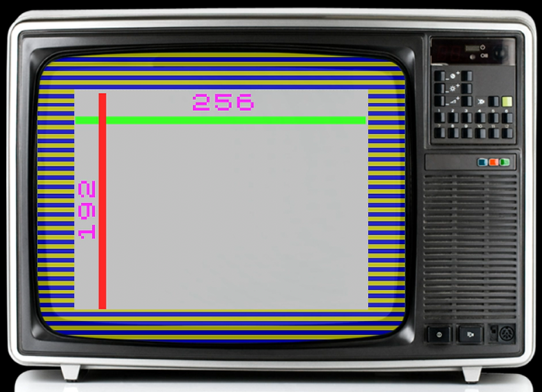
The layer 2 screen is 256×192 pixels, and uses 8 bit colour. The colour is defined using R3G3B2 format which means 8 bits are used per pixel, with the first three bits defining how much red is used, then three bits for green and finally two bits for blue.
A tiny bit of code done using a C macro will pack an RGB value into the byte representing the pixel.
#define RGB2COLOUR(r,g,b) (uint8_t)(((r & 0x7) << 5) | ((g & 0x7) << 2) | (b & 0x3))Code language: PHP (php)The screen is defined as one continuous block of 48K, it isn’t interleaved like the original Spectrum’s display was. Also it isn’t stored in any special video memory, there is no need to copy the screen data to video memory. Writing pixels to the ram used by the video hardware is identical to writing to any other part of RAM.
The 48K of screen memory won’t fit into the Z80’s address space though, if you try it would fill up all the RAM leaving no room for any program code. To get around this, the screen is split into three pieces and the relevant part is banked into memory.
A pixel plotting routine that does this is given below
void layer2_plot(uint8_t x, uint8_t y, uint8_t colour)
{
   uint8_t newy = y;
   // Work out which bit of screen we need
   if (y >= 128) {
      IO_123B = 0x83;   // Bottom
      newy -= 128;
   } else if (y >= 64) {
      IO_123B = 0x43;   // Middle
      newy -= 64;
   } else {
      IO_123B = 0x03;   // Top
   }
   *(uint8_t*)(x + (newy << 8)) = colour;
}Code language: JavaScript (javascript)
The specifics of how this works is in another post.